Bending
We are happy to bend a variety of materials using our precision CNC press brake machine. We have some general guidelines below. If you have any questions on bending you can always reach us at
At a glance
- No minimum order quantity
- Not all of our materials are available for bending. Check the table below
- ± 1 degree bend tolerance
- ± 0.015" length tolerance
- Minimum flange length: Varies based on material thickness
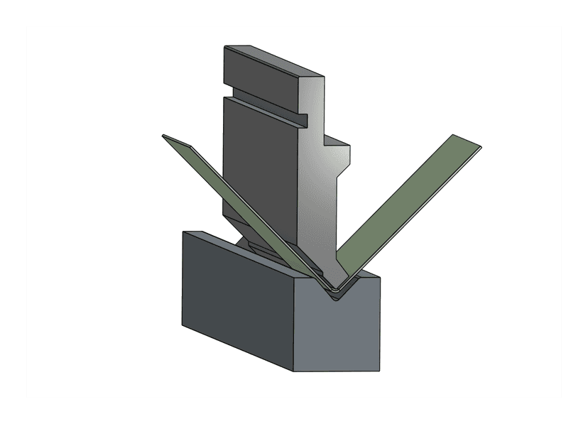
How Bending Works
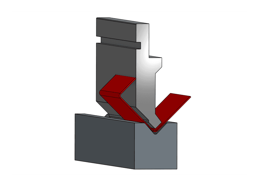
We use a CNC press brake to create accurate bends in your sheet metal parts. The process presses your material between two specially shaped tools - a punch and a die - to create precise angles. Our CNC-controlled system ensures consistent, repeatable results across multiple parts. Here's a detailed look at how it works:
The Die

The die is the bottom tool with a V-shaped opening that supports and forms the material. Different dies are used for different materials and thicknesses.
The Punch
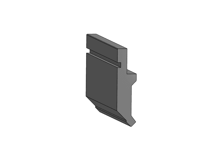
The punch is the top tool that presses the material into the die, creating precise bends. Its tip determines the inside radius of the bend.
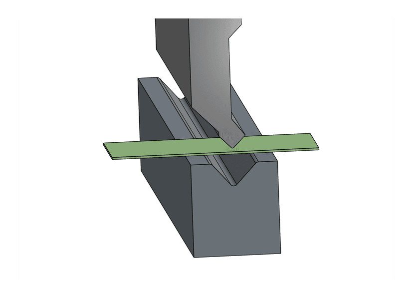
1. We position your part on the die using CNC backgauges so we know the bend is located properly
2. The punch descends and presses your part between the punch and the die, forming the correct angle.
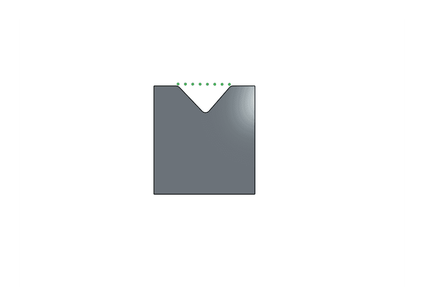
Good to know: Die Opening / Die Width
When designing your parts for bending, you should consider the die width. The die opening (or die width) is the distance between the two sides of the V-shaped die.
Features within one die opening distance from the bend line may be deformed during bending.
Flanges that are too close to the bend line may be deformed during bending. The part needs to be fully supported by the die on either side of the bend line to form properly
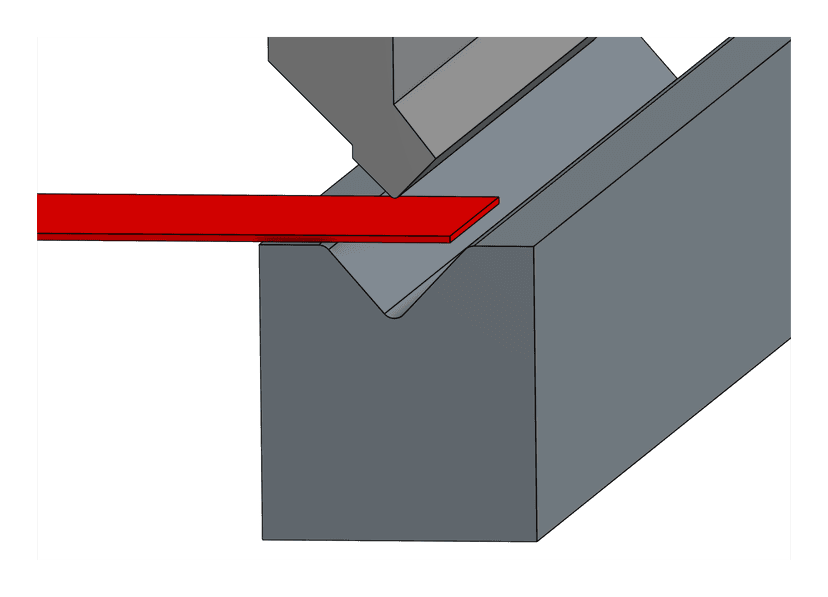
Angles
How We Measure Angles
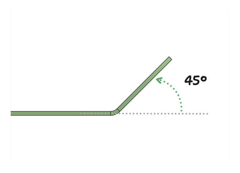
Bend angles can be confusing at first glance. While the example might look like a 135° angle, it's actually a 45° bend. Here's why:
- Bend angles are measured from the original flat position (shown by the gray line)
- The angle represents how far the flange was bent up from flat
- In this case, the flange was bent up 45° from its original flat position
This is the standard way bend angles are measured in sheet metal fabrication. We handle showing the correct angle by default when you upload your .STEP file
We can create bends from 1° up to 90°. Angles greater than 90° or hemmed edges are not possible with our current tooling.
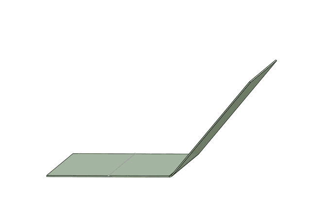
50° bend - A typical acute angle bend
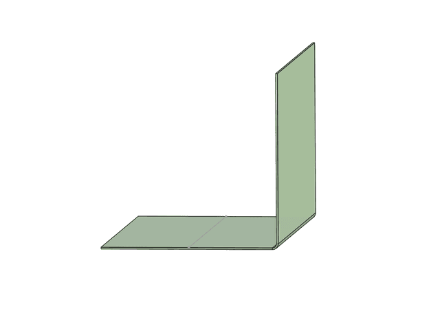
90° bend - The maximum angle we can achieve
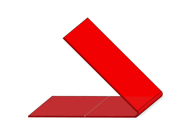
135° bend - Angles over 90° cannot be formed
Hemmed edge - We cannot create hemmed edges
Flange Length
The flange length (the part being bent up) must be long enough to be properly supported by the die during bending. Insufficient flange length can lead to distortion and inconsistent bend angles.
Minimum Flange Length: The minimum flange length varies based on the material thickness you select. Our system will automatically check your flange lengths once you select a material.
Before Bending
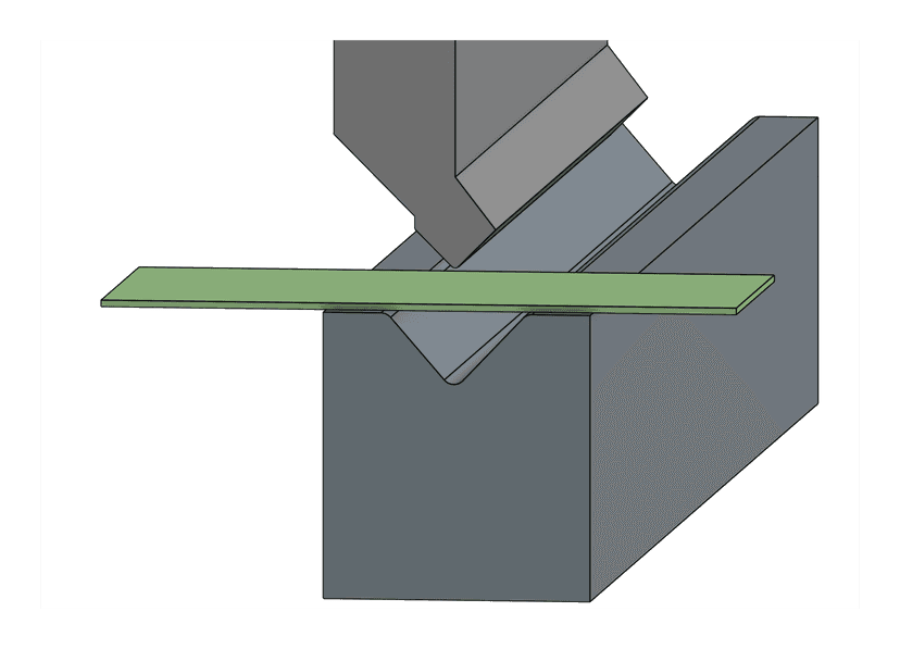
✅ Flange fully supported by the die before bending
After Bending
✅ Results in a clean, accurate bend
Before Bending
❌ Flange not fully supported by the die
After Bending
❌ Results in distortion and inconsistent bend angle
Design Tip: We recommend designing flanges at least 4 times the material thickness for optimal results. Our system will validate your flange lengths against the specific die opening required for your selected material.
Flange Too Short: If your part shows a "Not Manufacturable" error mentioning flange length, you can try selecting a different material/thickness combination that uses a smaller die opening, or redesign your part with longer flanges.
Distortion
Feature distortion occurs when holes, slots, or other features are placed too close to a bend line. To prevent distortion, keep features at least 2 times the material thickness plus the bend radius (2t + r) away from any bend line.
❌ This hole is within the die opening distance and will become oval-shaped during bending
✅ This hole is safely outside the die opening distance and will remain round
Design Tip: For example, a 2mm thick material with a 2mm bend radius requires features to be at least 6mm (2×2 + 2) from the bend line. Thicker materials need more clearance.
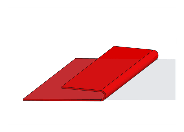
U-Channel Design
When designing U-channel parts (parts with two parallel bends), the ratio between the base and side flanges is crucial. A 3:1 ratio between the base and flanges helps prevent tool collision and ensures consistent bending.
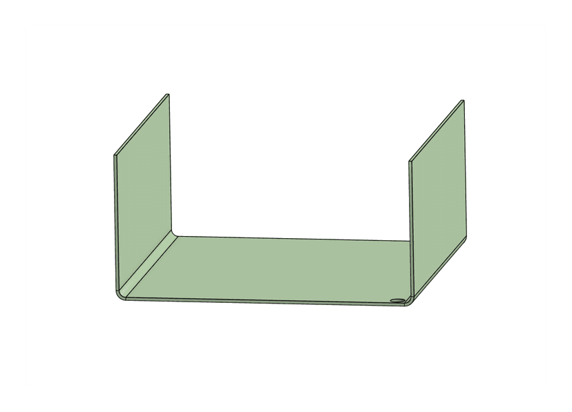
✅ Base is 3x longer than flanges, allowing easy tool access
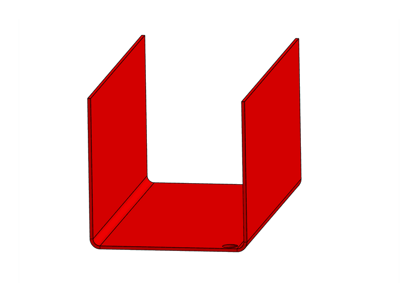
❌ Base too short relative to flanges, making bending difficult
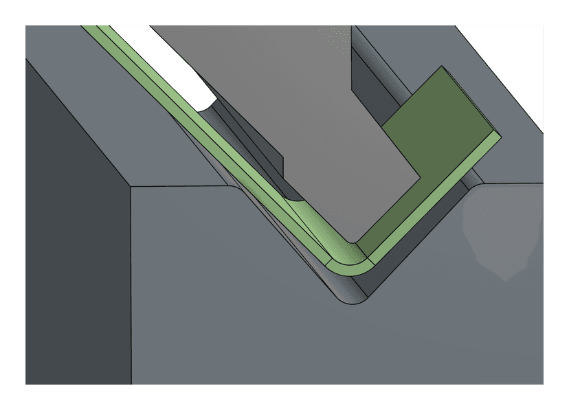
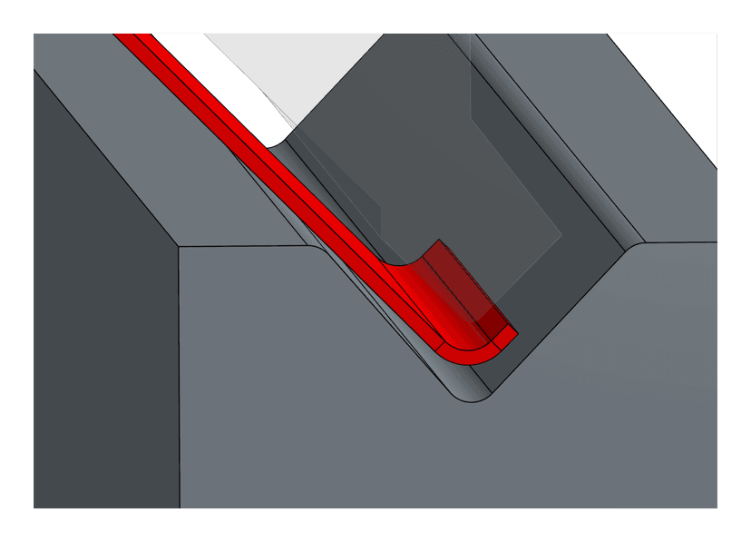
Tool Collision
When U-channels are too narrow, the punch can collide with the already bent flange. Here's what that looks like in profile and in 3D:
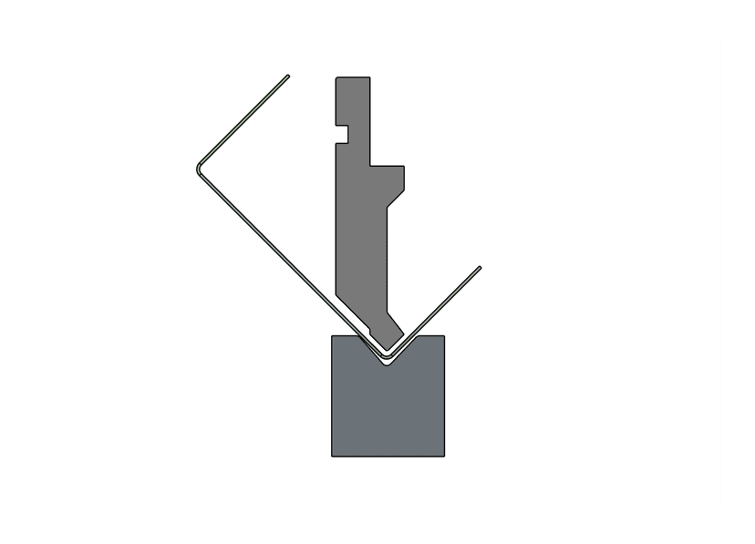
✅ Sufficient space between punch and first bend
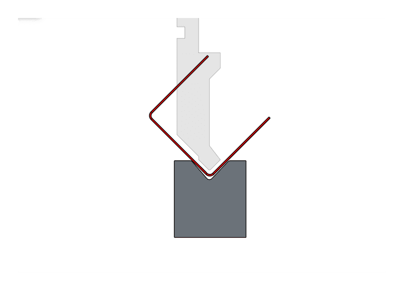
❌ Punch collides with first bend during second operation
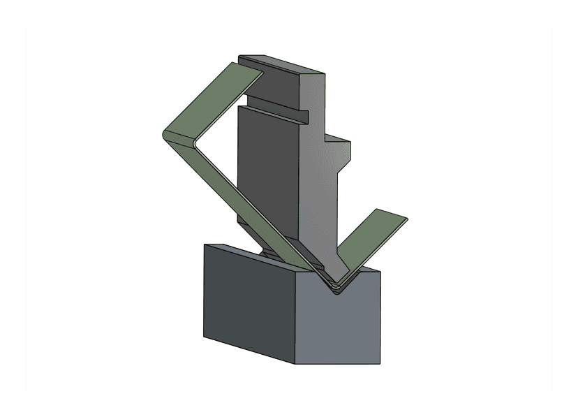
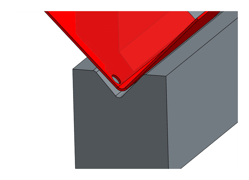
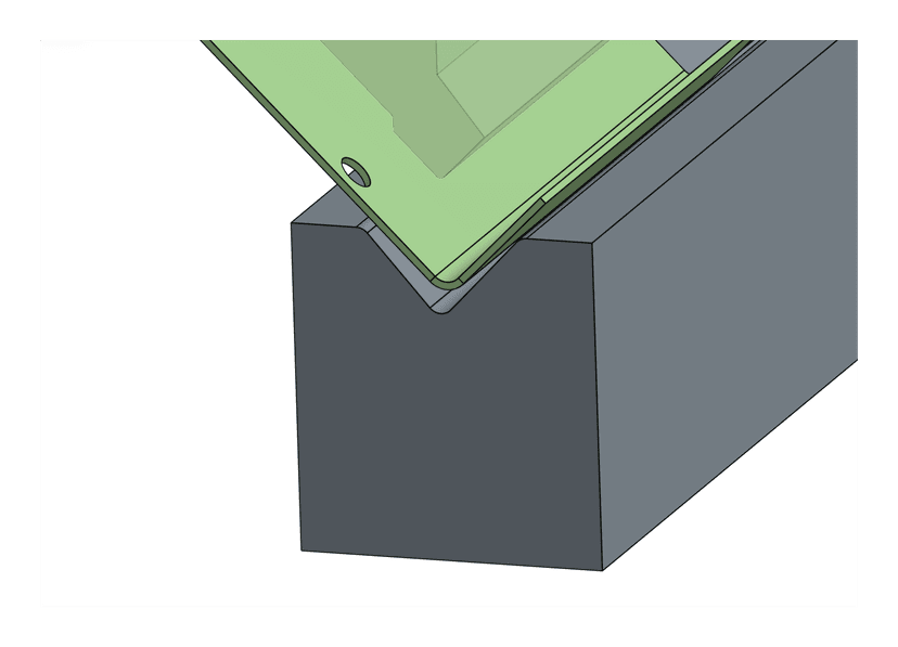
✅ 3D view showing proper tool clearance
❌ 3D view showing tool interference
Design Tip: When designing U-channel parts, aim for a base length at least 3 times the height of your flanges. This ensures proper tool clearance and consistent bend quality.
Press Brake Tonnage Limits
Our press brake has a maximum capacity of 70 tons. The force required to bend your part depends on three factors: material type, material thickness, and bend length. If a bend exceeds our tonnage capacity, we won't be able to manufacture the part.
How Tonnage Is Calculated
The required tonnage for a bend is calculated using this formula:
Where F is a base tonnage value (tons per lineal foot) determined by the material thickness and the die opening we use.
Material Multipliers
Different materials require different amounts of force to bend. Relative to mild steel:
Aluminum
0.5×
Requires half the force of steel
Steel
1.0×
Baseline reference
Stainless Steel
1.5×
Requires 50% more force than steel
What Affects Tonnage?
- Bend length: Longer bends require more force. A 60" bend requires 5× the tonnage of a 12" bend.
- Material thickness: Thicker materials require significantly more force. Doubling thickness can quadruple the required tonnage.
- Material type: Stainless steel requires 3× the force of aluminum for the same bend.
Tonnage Exceeded: If your part shows a "Not Manufacturable" error mentioning tonnage, try one of these solutions:
- Reduce the bend length by splitting into multiple parts
- Use a thinner material if your design allows
- Switch to aluminum instead of steel or stainless
We automatically review all parts for manufacturability when you submit them. If we spot any potential issues, we'll email you right away with suggestions.
Can't find what you're looking for? Have questions about your design? We're happy to help! Reach out anytime at